Worm Gear Motor Explained: The Complete Guide
-
 2026.09.21
-
Uncategorized


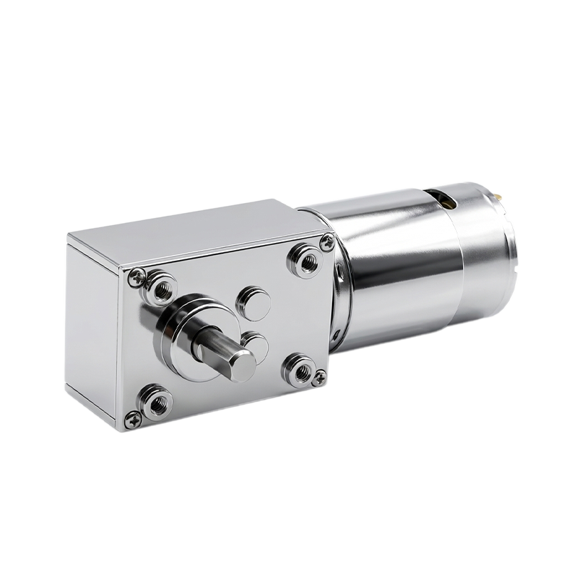
A worm gear motor pairs a DC or stepper motor with a worm gearbox — a screw-shaped worm meshing with a toothed wheel — to cut speed and multiply torque through a single 90° stage. Recognizing that mechanism on a spec sheet is the first step to judging whether it fits a design that needs holding torque, a right-angle shaft, or a compact reduction stage.
What Is a Worm Gear Motor?
A worm gear motor is a DC or stepper motor combined with a worm gearbox — a screw-shaped worm meshing with a toothed worm wheel — to convert the motor's high rotational speed into low-speed, high-torque output at a right angle. The motor itself doesn't change; it's the same brushed, coreless, or stepper drive found in other gear motor types. What differs is the transmission stage on its output shaft: instead of a stack of small spur or planetary gears, a single hardened screw thread does the speed reduction.
This single-stage design is why worm gear motors show up wherever a design needs a large speed drop, a 90° direction change, and a shaft that resists being pushed backward — all from one compact housing.
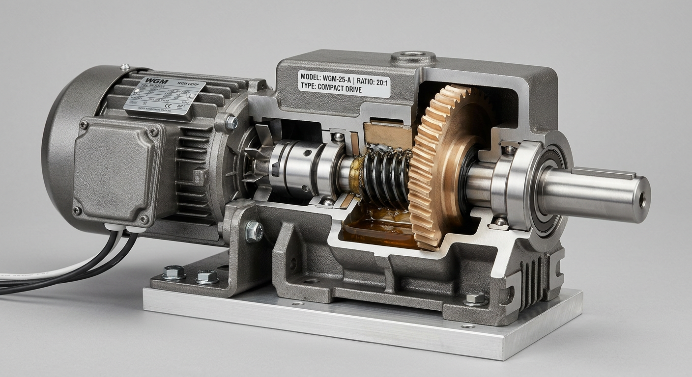
The Anatomy of a Worm Gear Motor
Three parts do the work:
- The motor — the electrical drive (brushed DC, coreless DC, or stepper) supplying rotational input.
- The worm — a screw-shaped gear on the motor's output shaft. Its thread acts like a continuous, spiraling tooth.
- The worm wheel — a circular gear cut to match the worm's thread angle, sitting perpendicular to it so the input and output shafts meet at roughly 90°.
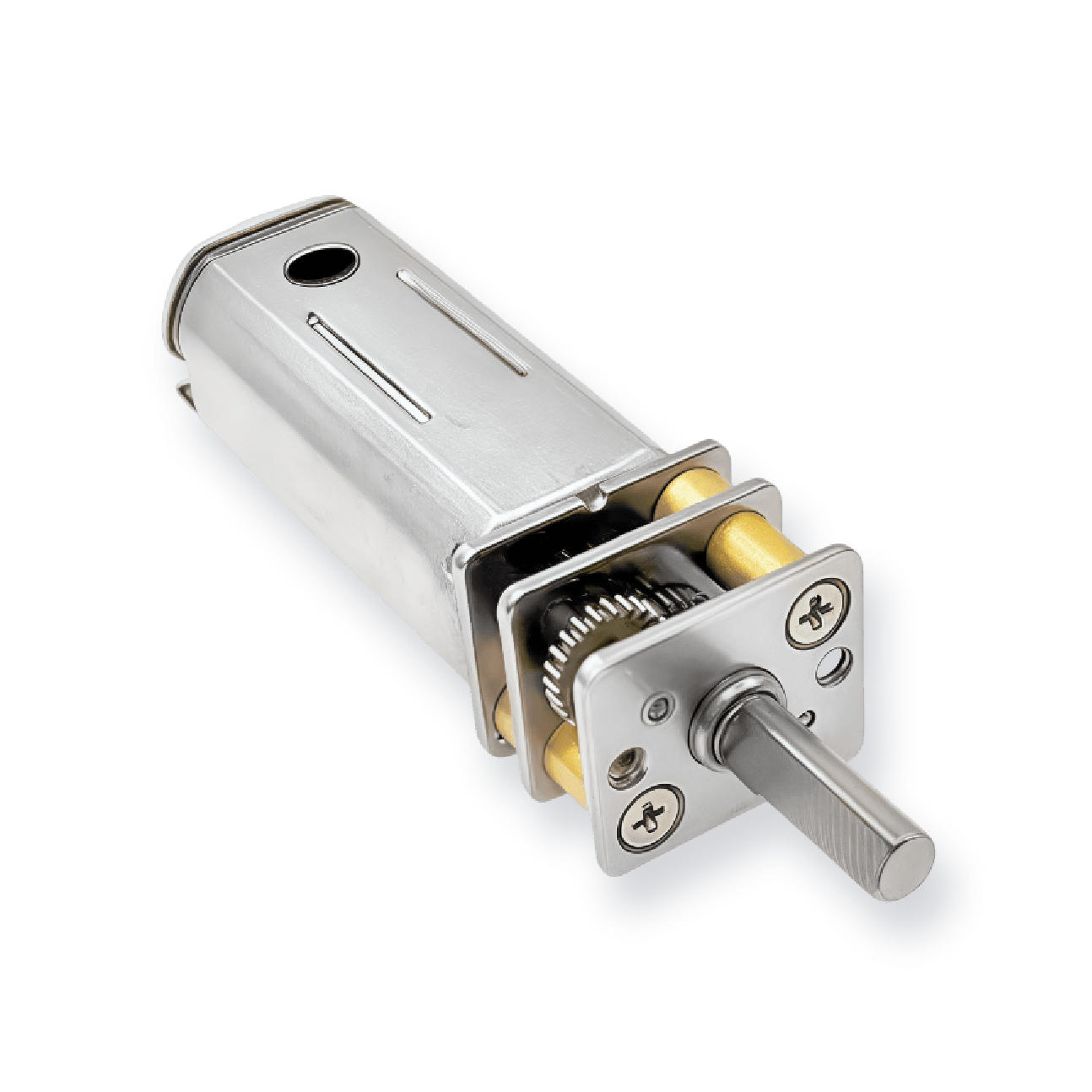
That right-angle layout is the visual giveaway: if a gear motor's output shaft exits perpendicular to the motor body rather than straight out the back, it's a worm gear motor. The 18mm Worm Gearbox & Reducer shows the worm and wheel housed as a standalone reduction unit that can pair with different motor types.
What Is the Purpose of Worm Gears?
Worm gears exist to solve three problems in a single mechanical stage: large speed reduction with torque multiplication, a 90° shaft turn, and self-locking behavior.
- Speed reduction / torque multiplication. A worm engages many wheel teeth per revolution instead of one tooth at a time, giving a larger reduction than a comparable spur gear pair in the same footprint. Single-stage worm gearing typically spans 5:1 to 100:1.
- A 90° shaft turn. Because the worm and wheel axes are perpendicular, worm gearing routes power around a corner without a separate bevel gear stage.
- Self-locking. Below roughly a 5° worm lead angle, friction at the thread resists the wheel driving the worm backward, so the output can hold a load without a brake. Above that lead angle, back-driving becomes possible — self-locking should be confirmed for the specific ratio, not assumed for every worm gearbox.
How a Worm Gear Motor Works (Step by Step)
- The motor spins the worm at its native RPM.
- The worm's spiral thread pushes against the wheel's teeth. A single-start worm — one continuous thread — advances the wheel by exactly one tooth per full worm revolution.
- The ratio equals the number of wheel teeth divided by the number of thread starts on the worm: a 40-tooth wheel driven by a single-start worm gives 40:1; the same wheel driven by a 4-start worm gives 10:1.
- The wheel's shaft delivers that reduced speed and multiplied torque as the gearbox output.
Key Characteristics of Worm Gear Motors
- High single-stage reduction — commonly 5:1 to 100:1 from one worm-and-wheel pair.
- Self-locking below a low lead angle — generally under ~5°, resisting back-drive without a separate brake.
- Moderate efficiency — typically 40–90%, lower than planetary gearing's 90%+, because sliding contact between worm and wheel converts some input energy to heat.
- Quiet, smooth meshing — sliding contact tends to run smoother and quieter than tooth-on-tooth spur meshing.
- Compact right-angle form factor — the 90° layout saves space where a straight-through gear motor wouldn't fit.
- Deliberate material pairing — the worm is typically hardened steel; the wheel is a softer material, commonly bronze or an engineering polymer. Pairing a hard worm with a softer wheel concentrates wear on the cheaper, easier-to-replace part and lowers friction against steel, partly offsetting the efficiency loss from sliding contact.
A configuration built on these principles is the 12mm Coreless Motor with Worm Gearbox. For help matching a ratio and material pairing to a specific load, contact SLW Motor's engineering team.
Small-Envelope Worm Gear Motors (8mm–18mm)
Worm gearing scales down further than most engineers expect. Worm-driven stages exist in housings as small as 8mm, such as the 8mm stepper motor with worm gearbox, up through 12mm coreless-motor worm gearboxes and an 18mm worm gearbox reducer built as a standalone unit. At this scale, self-locking matters just as much as in larger drives — a small positioning stage still needs to hold its position without drawing continuous current.
Holding capacity in any worm-driven stage is rated the same way as other DC gear motor output: by stall torque at the output shaft. SLW's 20mm 180 micro brushed DC motor, for example, is rated up to 235.6 g·cm of stall torque at 24V before a worm gearbox multiplies that further — the same stall-torque metric used to size holding capacity once a reduction stage is added.
Common Applications of Worm Gear Motors
Worm gear motors turn up wherever a design needs holding torque without a brake, a right-angle drive path, or a large reduction in a small space:
- Robotics joints and actuators, holding position under load between moves.
- Automation equipment, for right-angle drive stages in tight machine layouts.
- Medical devices, where quiet, self-locking motion suits positioning stages.
- Precision equipment that must hold a set position without continuous power.
Worm Gear Motors vs. Other Gear Motor Types
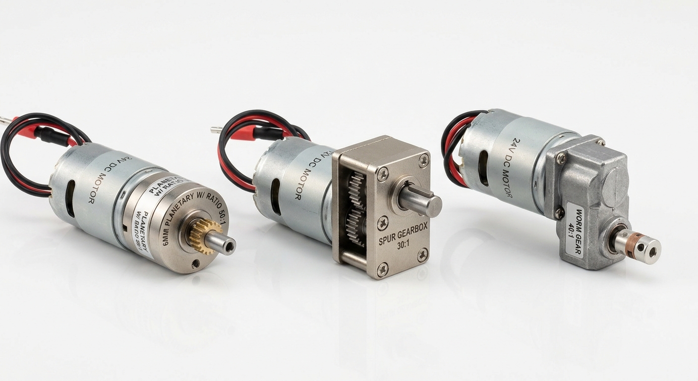
Worm gearing isn't the only way to reduce speed and multiply torque. Spur and planetary gear motors solve the same problem with different trade-offs in efficiency, precision, and shaft layout. If the priority is maximum efficiency or backlash-free precision rather than self-locking and a 90° shaft, a planetary gear motor is usually the better starting point — the planetary gear motor guide breaks down that mechanism.
How to Choose the Right Worm Gear Motor
- Required torque and speed at the load, not just at the motor shaft.
- Voltage available in the system — match the drive electronics first.
- Holding-torque or self-lock need — a real requirement if the load must stay put with power off.
- Size envelope — the 90° shaft layout needs clearance in a different direction than a straight-through gear motor.
- Material pairing — hardened steel worms with bronze or polymer wheels suit different load, wear, and cost profiles.
Once torque, voltage, and envelope are set, browse SLW's full range of worm gear motors to compare specs and configurations, or contact SLW Motor's team directly for a custom ratio, shaft, or housing material. For a closer look at what self-locking costs in efficiency and when it's worth it, see worm gear motor pros and cons, and for holding-force numbers, worm gear motor self-locking and holding force.
Frequently Asked Questions
What is a worm gear motor?
A worm gear motor is a motor paired with a worm gearbox, where a screw-shaped worm meshes with a toothed worm wheel to reduce speed, multiply torque, and turn the output shaft roughly 90° from the input.
What is the purpose of worm gears?
Worm gears deliver a large speed reduction in a single stage, allow a 90° change in shaft direction, and generally create self-locking behavior below a low worm lead angle — letting the worm drive the wheel while resisting the wheel driving the worm backward.
What is the difference between a worm gear and a regular gear?
A regular (spur) gear meshes tooth-to-tooth with another gear on a parallel shaft through rolling contact. A worm gear uses a screw-shaped worm meshing with a wheel on a perpendicular shaft through sliding contact, which enables the 90° turn and self-locking that spur gears don't provide.
What are worm gear motors used for?
Common uses include robotics joints and actuators, automation equipment needing a right-angle drive, medical device positioning stages, and precision equipment that must hold position without continuous power thanks to self-locking.