Hall Sensor Brushless Motors

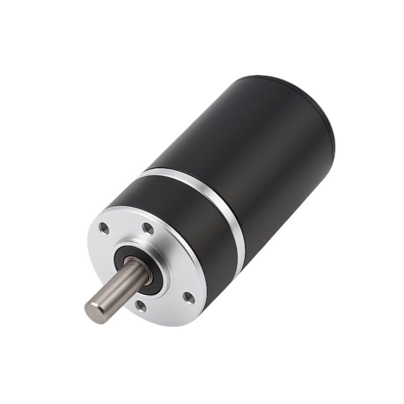
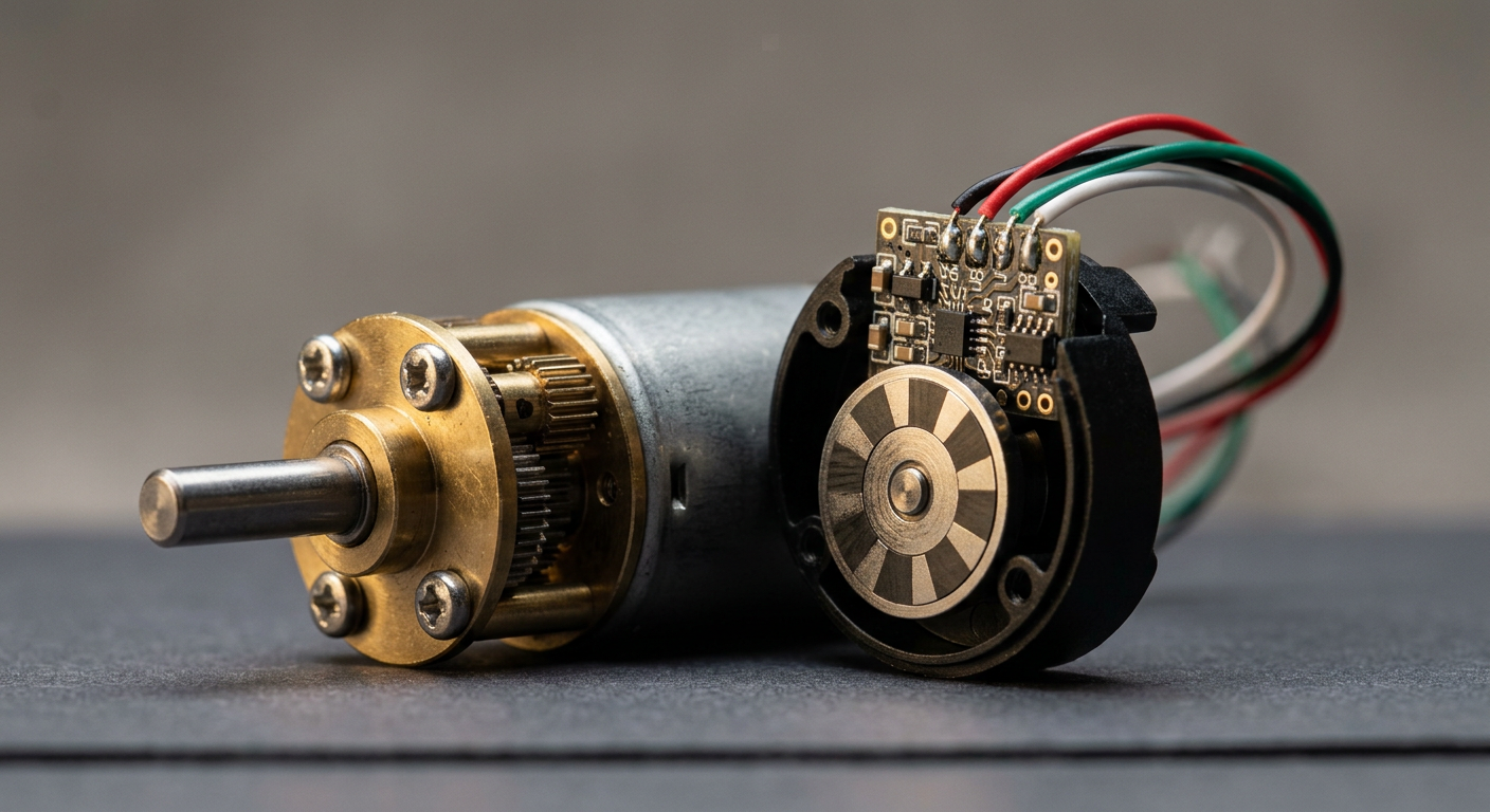
A Hall sensor brushless motor — a sensored BLDC motor — carries three Hall-effect sensors in the stator so the driver knows rotor position before the first commutation step. We build Hall sensor brushless motors across our 16mm–60mm BLDC frame sizes, with three Hall-effect sensors built into the stator for reliable low-speed starting torque and simple six-step commutation.

Hall Sensor Brushless Motors Featured Image
Feedback Options

Sensored vs Sensorless vs Encoder

Hall sensor feedback sits between sensorless control and full encoder feedback: it costs more than sensorless, but far less than an encoder, and delivers predictable torque at zero and low speed.

SensorlessHall SensorEncoder
Startup torque reliabilityCan stall or jerk at zero/low speed; relies on back-EMF sensing that isn't available at standstillReliable — rotor position is known before the first phase switchReliable, plus precise position/speed data throughout the range
WiringMotor phase wires only (typically 3)Phase wires + 3 Hall signal wires + sensor power/ground (commonly 5–6 total)Phase wires + encoder channel wires (often more conductors than Hall)
Typical use caseFans, pumps, and other loads that don't need accurate low-speed controlPumps, actuators, robotic joints, and equipment needing dependable low-speed starting torquePositioning stages, closed-loop servo applications needing fine resolution
Relative cost/complexityLowestModerateHighest

For loads that run at speed once started, sensorless brushless motors are the better starting point, while fine-resolution closed-loop servo control calls for encoder-equipped BLDC motors.

Specifications

Frame Sizes & Performance Envelope

Hall-sensor commutation is built into our brushless DC motor line across the frame sizes and voltage classes below, with catalog datasheet values for the listed windings.

FrameVoltage Windings (applied range)No-Load SpeedTorque & Output at Max EfficiencyGearbox Option
16mm 1636 coreless BLDC12V / 24V (3–24V)12,000 rpm32.6 g·cm rated at 10,000 rpmPlanetary 14:1–1621:1
22mm BLDC12V / 18V / 24V (6–24V)3,100–8,600 rpm270–380 g·cm, 10–27.5W, up to 75.3% efficiencyPlanetary available
24mm BLDC9V / 12V / 24V (6–48V)5,400–8,700 rpm48.6–67.2 g·cm, up to 4.84WGearbox 4:1–500:1
28mm BLDC7.4V / 12V / 24V (6–48V)4,800–11,800 rpm90–156.8 g·cm, 3.6–16.5WPlanetary 4:1–625:1
36mm BLDC12V / 18V / 24V (6–48V)5,200–7,500 rpm175–209 g·cm, 7.4–12WPlanetary 3.7:1–721:1 or worm
42mm BLDC12V / 18V / 24V (6–48V)Per winding10–27WPlanetary 3.7:1–721:1
60mm BLDC12V / 18V / 24V (6–48V)Per winding10–27W, stall current 6.38–7.84ABare motor

These figures help you pick a starting frame size, not replace a real spec conversation. Contact SLW Motor with your target torque, speed, and duty cycle.

Sensored Feedback

What Hall Sensor Feedback Adds

  • Six-Step Commutation

    Three Hall ICs at 120° electrical intervals confirm rotor position before the motor starts moving.

  • Open-Collector vs Push-Pull

    The controller reads the sequence and drives the same stator and rotor phase switching that turns the motor. stator and rotor phase switching

  • Detection Methods

    Unipolar, omnipolar and bipolar latch detection shape the switching pattern the commutation circuit reads.

  • Temperature and Failure Modes

    Most field issues trace to wiring or the driver interface, not the motor.

Signal lines

Typical Motor Connections

Sensored BLDC motors commonly break out to a connector with these signal lines, though pinout and wire colors vary by manufacturer and should always be confirmed against the specific unit's datasheet:

SignalFunction
Sensor supply (commonly 5V)Powers the three Hall ICs
Hall U / Hall V / Hall WDigital position signals feeding the controller
Sensor groundCommon return for the Hall supply
Phase U / Phase V / Phase WMotor winding connections carrying drive current

Keep sensor supply and ground separate from the phase drive-current wiring to reduce switching noise on the low-level Hall signals.

Built-in Hall feedback

SLW Hall Sensor BLDC Motor Capabilities

  • Winding & voltage

    Hall-effect position sensing is built into our BLDC motor customization work, engineered into the winding and housing design, with torque, speed, voltage, and power configured around your load requirements.

  • Customization

    Shaft geometry, housing dimensions, and mounting details are adjusted case by case, with quiet operation, long life cycles, and environmental temperature resistance addressed at the design stage.

  • Materials & build

    Housing and gear materials are selected to match load and environment: brass, stainless steel, powder-metallurgy alloys, and engineering plastics are all available, standalone or paired with a gearbox.

  • Value-added integration

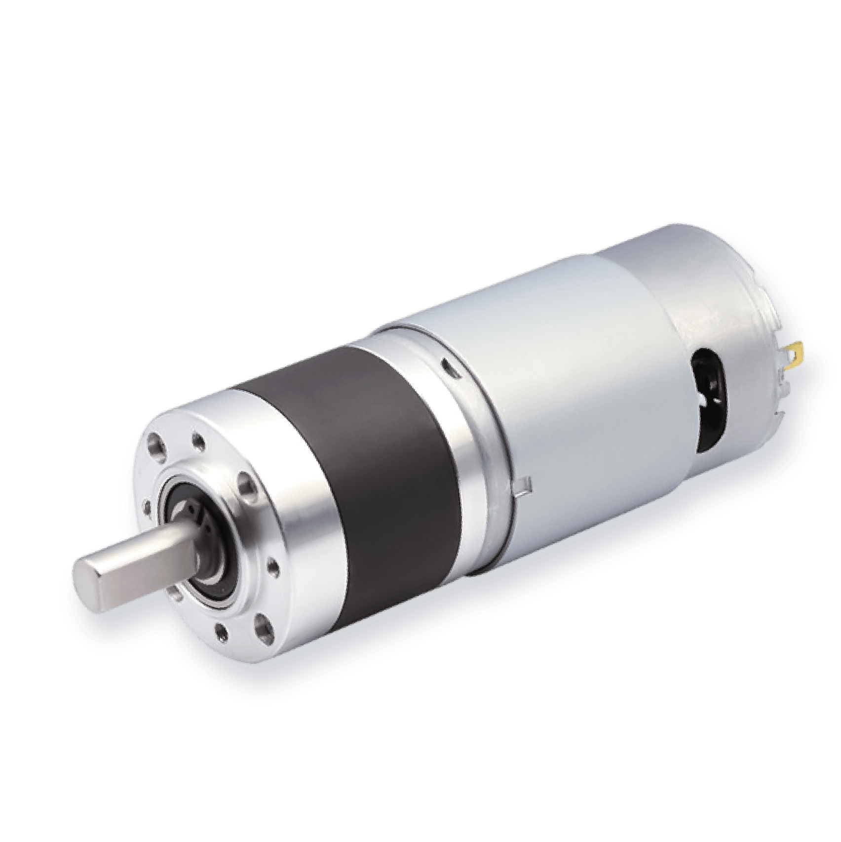
    We integrate encoder modules, PCB soldering, and harness assembly, and pair the motor with a planetary gear motor or worm gear motor stage.

Applications

Built for Precision Applications

  • Robotics

    Hall feedback gives the controller a known starting position, so the first move is correct in robotics motor applications where startup consistency is a spec requirement.

  • Automation

    Machines that start and stop frequently benefit from commutation that does not depend on the rotor already spinning, since sensorless back-EMF sensing is unreliable at restarts.

  • Medical

    A hesitant or jerky startup is not acceptable in patient-facing equipment; Hall feedback guarantees smooth starts without full encoder resolution, as in motors for medical equipment development.

  • Smart Devices

    Simple, low-wire-count commutation is preferable to a full encoder, and we pair Hall-sensor BLDC motors with coreless brushless options where low inertia and reliable startup torque matter.

Standards

Quality & Manufacturing Standards

SLW Motor is ISO 9001:2015 certified, with RoHS compliance documented for materials and components, and we operate our own factory in Shenzhen with more than 15 years of manufacturing and R&D experience. Every Hall sensor BLDC motor build goes through incoming inspection, in-process testing, and final verification, the same process control we apply across our full BLDC motor line.

  • Certified: ISO 9001:2015, with RoHS compliance documented
  • Own Factory: In-house Shenzhen plant with 56+ staff
  • Experience: 15+ years of manufacturing and R&D
  • Proven Trust: Projects for Japanese manufacturing customers
  • Process Control: Incoming, in-process, and final verification
Quote

How to Specify a Hall Sensor BLDC Motor

Send us your requirements and we'll confirm which frame size, winding, and sensor configuration fits your application.

  • Voltage

    Tell us your supply voltage or acceptable range so we can match the winding to your system.

  • Torque and Speed

    Share target operating torque and RPM at your load point, plus any startup torque requirement.

  • Frame Size

    Give us the maximum diameter and length your assembly can accommodate.

  • Hall Output

    Specify open-collector with your pull-up resistor spec, or push-pull, matched to your driver board.

  • Mounting and Shaft

    Include shaft diameter and length, flange or bracket mounting, and any gearbox pairing needed.

  • Connector and Harness

    Let us know whether you need bare leads, a specific connector housing, or a fully pre-terminated harness.

  • Environment

    Describe your operating temperature range, duty cycle, and any noise or life-cycle requirements.

With flexible sample customization through OEM/ODM engagements from prototype units through stable bulk delivery, Contact SLW Motor to start that conversation.

FAQ

FAQ

Answers on Hall sensor function, placement, output types, and ordering a sensored brushless motor.

What is a Hall sensor on a brushless motor?
It's a small embedded IC that detects rotor magnet position and outputs a digital signal, so the controller knows when to switch phase current for smooth starting torque.
Where do Hall sensors sit in a BLDC motor?
In a pre-built motor this is already engineered: three sensors sit internally around the stator at 120° electrical intervals, so their combined output changes every 60° of rotation.
What are the downsides of using Hall effect sensors?
You get a few extra signal wires and one more component that could fail versus a sensorless design, but the overhead is far smaller than adding a full encoder.
What are Hall sensors in a motor?
Solid-state magnetic sensors embedded near the stator that give the controller real-time rotor position feedback, enabling accurate low-speed starting torque and six-step commutation.

Open-collector or push-pull — which Hall output type do I need?
It depends on your driver board. Open-collector needs pull-up resistors on your controller side; push-pull drives the signal directly and usually needs no extra components.
What are typical lead times and minimum order quantities?
Lead time and minimum order quantity depend on the frame size, winding, and any gearbox or harness integration your build needs. Send your target specs through the quote form and we'll confirm both alongside pricing for your configuration.
Get Started

Accelerate Your Project with Precision Motors